- ホーム
- CompTIA
- N10-009J - CompTIA Network+ Certification Exam (N10-009日本語版)
- CompTIA.N10-009J.v2025-05-05.q68
- 質問64
有効的なN10-009J問題集はJPNTest.com提供され、N10-009J試験に合格することに役に立ちます!JPNTest.comは今最新N10-009J試験問題集を提供します。JPNTest.com N10-009J試験問題集はもう更新されました。ここでN10-009J問題集のテストエンジンを手に入れます。
N10-009J問題集最新版のアクセス
「792問、30% ディスカウント、特別な割引コード:JPNshiken」
シミュレーション
ネットワーク技術者がアクセス レイヤー スイッチを交換し、接続されたデバイスが正しいネットワークに接続できるように再構成する必要があります。
説明書
スイッチ 1 とスイッチ 3 の適切なポートをクリックして、正しい設定を確認または再構成します。
* 各デバイスが特定のデバイスのみにアクセスするようにする
正しく関連付けられたネットワーク。
* 未使用のスイッチポートをすべて無効にします。
フォールトトレラント接続を必要とする
スイッチ間。
必要な変更のみ行ってください
上記の要件を完了してください。
ネットワーク技術者がアクセス レイヤー スイッチを交換し、接続されたデバイスが正しいネットワークに接続できるように再構成する必要があります。
説明書
スイッチ 1 とスイッチ 3 の適切なポートをクリックして、正しい設定を確認または再構成します。
* 各デバイスが特定のデバイスのみにアクセスするようにする
正しく関連付けられたネットワーク。
* 未使用のスイッチポートをすべて無効にします。
フォールトトレラント接続を必要とする
スイッチ間。
必要な変更のみ行ってください
上記の要件を完了してください。
正解:
See the solution below in Explanation
Explanation:
To provide a complete solution for configuring the access layer switches, let's proceed with the following steps:
Identify the correct VLANs for each device and port.
Enable necessary ports and disable unused ports.
Configure fault-tolerant connections between the switches.
Configuration Details
Switch 1
Port 1 Configuration (Uplink to Core Switch)
Status: Enabled
LACP: Enabled
Speed: 1000
Duplex: Full
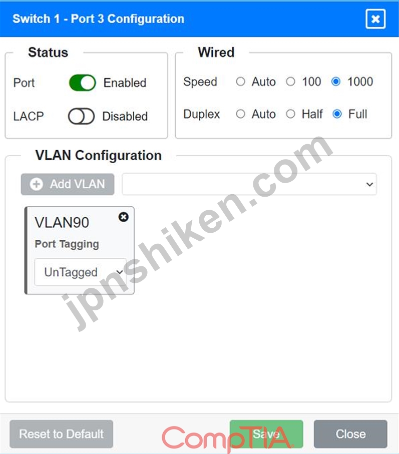
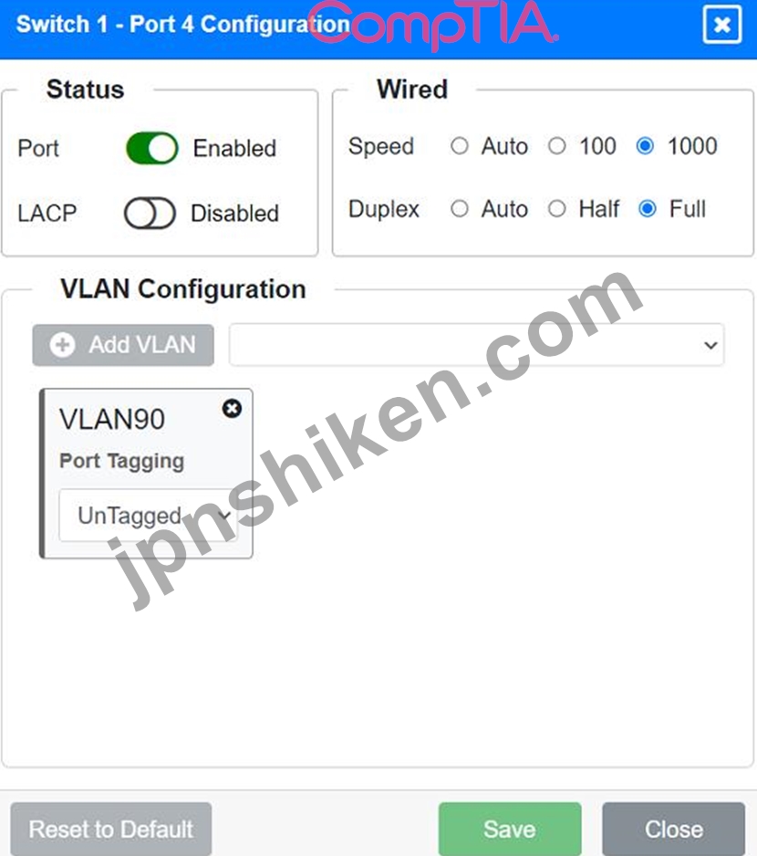
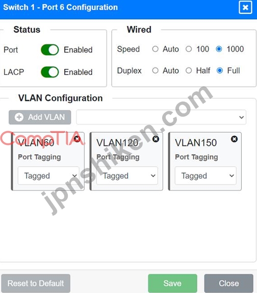
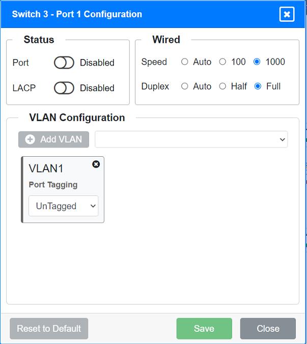
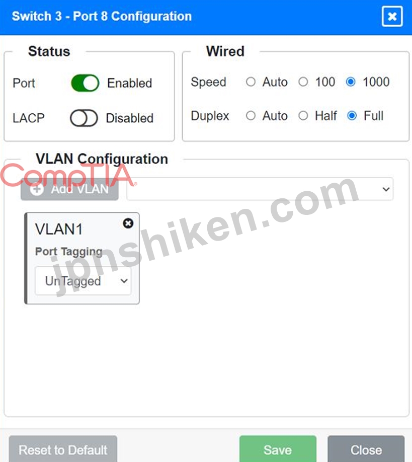
VLAN Configuration: Tagged for VLAN60, VLAN90, VLAN120, VLAN150, VLAN220 Port 2 Configuration (Uplink to Core Switch) Status: Enabled LACP: Enabled Speed: 1000 Duplex: Full VLAN Configuration: Tagged for VLAN60, VLAN90, VLAN120, VLAN150, VLAN220 Port 3 Configuration (Server Connection) Status: Enabled LACP: Disabled Speed: 1000 Duplex: Full VLAN Configuration: Untagged for VLAN90 (Servers) Port 4 Configuration (Server Connection) Status: Enabled LACP: Disabled Speed: 1000 Duplex: Full VLAN Configuration: Untagged for VLAN90 (Servers) Port 5 Configuration (Wired Users and WLAN) Status: Enabled LACP: Enabled Speed: 1000 Duplex: Full VLAN Configuration: Tagged for VLAN60, VLAN120, VLAN150 Port 6 Configuration (Wired Users and WLAN) Status: Enabled LACP: Enabled Speed: 1000 Duplex: Full VLAN Configuration: Tagged for VLAN60, VLAN120, VLAN150 Port 7 Configuration (Voice and Wired Users) Status: Enabled LACP: Enabled Speed: 1000 Duplex: Full VLAN Configuration: Tagged for VLAN60, VLAN90, VLAN120, VLAN220 Port 8 Configuration (Voice, Printers, and Wired Users) Status: Enabled LACP: Enabled Speed: 1000 Duplex: Full VLAN Configuration: Tagged for VLAN60, VLAN90, VLAN120, VLAN220 Switch 3 Port 1 Configuration (Unused) Status: Disabled LACP: Disabled Port 2 Configuration (Unused) Status: Disabled LACP: Disabled Port 3 Configuration (Connection to Device) Status: Enabled LACP: Disabled Speed: 1000 Duplex: Full VLAN Configuration: Untagged for VLAN1 (Default) Port 4 Configuration (Connection to Device) Status: Enabled LACP: Disabled Speed: 1000 Duplex: Full VLAN Configuration: Untagged for VLAN1 (Default) Port 5 Configuration (Connection to Device) Status: Enabled LACP: Disabled Speed: 1000 Duplex: Full VLAN Configuration: Untagged for VLAN1 (Default) Port 6 Configuration (Connection to Device) Status: Enabled LACP: Disabled Speed: 1000 Duplex: Full VLAN Configuration: Untagged for VLAN1 (Default) Port 7 Configuration (Connection to Device) Status: Enabled LACP: Disabled Speed: 1000 Duplex: Full VLAN Configuration: Untagged for VLAN1 (Default) Summary of Configurations Ports 1 and 2 on Switch 1 are configured as trunk ports with VLAN tagging enabled for all necessary VLANs.
Ports 3 and 4 on Switch 1 are configured for server connections with VLAN 90 untagged.
Ports 5, 6, 7, and 8 on Switch 1 are configured for devices needing access to multiple VLANs.
Unused ports on Switch 3 are disabled.
Ports 3, 4, 5, 6, and 7 on Switch 3 are enabled for default VLAN1.
Ensure All Switches and Ports are Configured as per the Requirements:
Core Switch Ports should be configured as needed for uplinks to Switch 1.
Ensure LACP is enabled for redundancy on trunk ports between switches.
By following these configurations, each device will access only its correctly associated network, unused switch ports will be disabled, and fault-tolerant connections will be established between the switches.
Explanation:
To provide a complete solution for configuring the access layer switches, let's proceed with the following steps:
Identify the correct VLANs for each device and port.
Enable necessary ports and disable unused ports.
Configure fault-tolerant connections between the switches.
Configuration Details
Switch 1
Port 1 Configuration (Uplink to Core Switch)
Status: Enabled
LACP: Enabled
Speed: 1000
Duplex: Full
VLAN Configuration: Tagged for VLAN60, VLAN90, VLAN120, VLAN150, VLAN220 Port 2 Configuration (Uplink to Core Switch) Status: Enabled LACP: Enabled Speed: 1000 Duplex: Full VLAN Configuration: Tagged for VLAN60, VLAN90, VLAN120, VLAN150, VLAN220 Port 3 Configuration (Server Connection) Status: Enabled LACP: Disabled Speed: 1000 Duplex: Full VLAN Configuration: Untagged for VLAN90 (Servers) Port 4 Configuration (Server Connection) Status: Enabled LACP: Disabled Speed: 1000 Duplex: Full VLAN Configuration: Untagged for VLAN90 (Servers) Port 5 Configuration (Wired Users and WLAN) Status: Enabled LACP: Enabled Speed: 1000 Duplex: Full VLAN Configuration: Tagged for VLAN60, VLAN120, VLAN150 Port 6 Configuration (Wired Users and WLAN) Status: Enabled LACP: Enabled Speed: 1000 Duplex: Full VLAN Configuration: Tagged for VLAN60, VLAN120, VLAN150 Port 7 Configuration (Voice and Wired Users) Status: Enabled LACP: Enabled Speed: 1000 Duplex: Full VLAN Configuration: Tagged for VLAN60, VLAN90, VLAN120, VLAN220 Port 8 Configuration (Voice, Printers, and Wired Users) Status: Enabled LACP: Enabled Speed: 1000 Duplex: Full VLAN Configuration: Tagged for VLAN60, VLAN90, VLAN120, VLAN220 Switch 3 Port 1 Configuration (Unused) Status: Disabled LACP: Disabled Port 2 Configuration (Unused) Status: Disabled LACP: Disabled Port 3 Configuration (Connection to Device) Status: Enabled LACP: Disabled Speed: 1000 Duplex: Full VLAN Configuration: Untagged for VLAN1 (Default) Port 4 Configuration (Connection to Device) Status: Enabled LACP: Disabled Speed: 1000 Duplex: Full VLAN Configuration: Untagged for VLAN1 (Default) Port 5 Configuration (Connection to Device) Status: Enabled LACP: Disabled Speed: 1000 Duplex: Full VLAN Configuration: Untagged for VLAN1 (Default) Port 6 Configuration (Connection to Device) Status: Enabled LACP: Disabled Speed: 1000 Duplex: Full VLAN Configuration: Untagged for VLAN1 (Default) Port 7 Configuration (Connection to Device) Status: Enabled LACP: Disabled Speed: 1000 Duplex: Full VLAN Configuration: Untagged for VLAN1 (Default) Summary of Configurations Ports 1 and 2 on Switch 1 are configured as trunk ports with VLAN tagging enabled for all necessary VLANs.
Ports 3 and 4 on Switch 1 are configured for server connections with VLAN 90 untagged.
Ports 5, 6, 7, and 8 on Switch 1 are configured for devices needing access to multiple VLANs.
Unused ports on Switch 3 are disabled.
Ports 3, 4, 5, 6, and 7 on Switch 3 are enabled for default VLAN1.
Ensure All Switches and Ports are Configured as per the Requirements:
Core Switch Ports should be configured as needed for uplinks to Switch 1.
Ensure LACP is enabled for redundancy on trunk ports between switches.
By following these configurations, each device will access only its correctly associated network, unused switch ports will be disabled, and fault-tolerant connections will be established between the switches.

- 質問一覧「68問」
- 質問1 ネットワーク技術者が、Web アプリケーションのパフォーマンス低...
- 質問2 ある企業は、短期間のダウンタイムを許容できる災害復旧サイトま
- 質問3 ネットワーク管理者は、2 台のルーターをポイントツーポイント構...
- 質問4 ファイアウォールに変更を加えた後、ユーザーは Web サーバーに...
- 質問5 ネットワーク技術者がアクセス ポートの設定を調べているときに
- 質問6 ネットワーク エンジニアが新しいメール サーバーへの移行を実行...
- 質問7 次のネットワーク トラフィック タイプのうち、ネットワーク上の...
- 質問8 小規模オフィスのネットワーク管理者は、ネットワーク トラフィ
- 質問9 根本原因理論のテストに成功した後に実行する次のステップはどれ
- 質問10 スプリット トンネル VPN のコスト効率の面での利点は次のどれで...
- 質問11 シミュレーション 最近、ネットワーク技術者が会社に入社しまし
- 質問12 技術者が、オフィスビルの新棟で働くユーザーのコンピューターの
- 質問13 ネットワーク エンジニアは、拡張と冗長性のために新しいスイッ
- 質問14 顧客は 6 つの使用可能な IP アドレスを必要としています。この...
- 質問15 会社の会計担当者が財務部門の共有フォルダしか閲覧できない場合
- 質問16 ある会社では、サーバーへのすべての接続を暗号化する必要がある
- 質問17 会社のビルのフロアにあるすべてのネットワーク ケーブルの中央
- 質問18 コネクションレス通信上のトランスポート層で発生する伝送形式を
- 質問19 ゲスト ネットワークを使用する前に、管理者はユーザーに使用条
- 質問20 ネットワーク管理者は、新しくインストールしたネットワークに I...
- 質問21 3 つのアクセス ポイントには、天井を通るイーサネットがありま...
- 質問22 最後のバックアップ以降に失われたデータの量を表すために使用さ
- 質問23 ネットワーク管理者は、35 台の PoE セキュリティ カメラを設置...
- 質問24 次の攻撃のうち、複数のネットワーク タグを含むネットワーク パ...
- 質問25 トラブルシューティング方法論の次のステップのうち、原因を特定
- 質問26 ある組織では、すべてのネットワーク接続をユーザーまでさかのぼ
- 質問27 ネットワーク エンジニアは、スイッチと LAN に接続されたルータ...
- 質問28 システム管理者は、ユーザーがブラウザで Linux Web サーバーに...
- 質問29 ネットワーク管理者は、ユーザーが正規のサイトを装ったマルウェ
- 質問30 ある研究施設では、近い将来、世界的なネットワークトラフィック
- 質問31 次の災害復旧の概念のうち、総稼働時間を総ユニット数で割って計
- 質問32 攻撃の一環として、脅威の攻撃者はスイッチ上のコンテンツ アド
- 質問33 仮想マシンの構成は次のとおりです。 *IPv4アドレス: 169.254.10...
- 質問34 ある会社の最高経営責任者 (CEO) が、さまざまな国を旅行すると...
- 質問35 ネットワーク管理者は、ネットワークの可視性を高めるためにデバ
- 質問36 次のアプライアンスのうち、指定された WLAN 内の複数のデバイス...
- 質問37 ある組織では、受信メールが信頼できるソースから送信されたこと
- 質問38 X.509 証明書が最も一般的に関連付けられているテクノロジは次の...
- 質問39 設置するラックのサイズを決定する要因として最も可能性が高いの
- 質問40 次のどれが、単一のクラウド アカウント内でのコンピューティン
- 質問41 ある会社がネットワークと PC をギガビット速度にアップグレード...
- 質問42 ストレージ ネットワークでは、送信されるデータ量に対するオー
- 質問43 最近の侵害を受けて、クライアントは全体的なセキュリティを強化
- 質問44 ネットワーク管理者は各部門にセキュリティ ゾーンを実装してい
- 質問45 次のどれがジャンボ フレームをサポートできますか?
- 質問46 シミュレーション ネットワーク管理者は、新しい企業オフィスの
- 質問47 技術者は、ホット アイル/コールド アイル換気を実践しているデ...
- 質問48 ユーザーの VoIP 電話とワークステーションは、インライン ケー...
- 質問49 ネットワーク管理者は、会社のアプリケーションをクラウドでホス
- 質問50 システム管理者は、ネットワークに追加する新しいデバイスを構成
- 質問51 シミュレーション ネットワーク技術者は、顧客の SOHO ネットワ...
- 質問52 次のどれが実装時にセキュリティ機能も提供できますか?
- 質問53 トラブルシューティング方法論の次の手順のうち、最近の変更につ
- 質問54 次のルーティング プロトコルのうち、自律システム番号を使用す
- 質問55 ネットワーク エンジニアが新しい建物でワイヤレス インストール...
- 質問56 次のどれがクラウド環境への専用リンクに最も密接に関連し、暗号
- 質問57 会社の本社と支店を安全に接続するには、次のどれを実装する必要
- 質問58 次の攻撃のうち、ネットワーク内で IP アドレスの重複を引き起こ...
- 質問59 ネットワーク技術者は、新しく入居したオフィスのアクセス スイ
- 質問60 シミュレーション ネットワーク セキュリティを確保するために、...
- 質問61 IT マネージャーは、メッシュ ネットワークで 10 個のサイトを接...
- 質問62 シミュレーション ネットワーク技術者は、顧客の SOHO ネットワ...
- 質問63 保険仲介業者が VPN の使用を強制する理由として最も可能性が高...
- 質問64 シミュレーション ネットワーク技術者がアクセス レイヤー スイ...
- 質問65 ネットワーク管理者は、ネットワーク内の 2 つのレイヤー 2 スイ...
- 質問66 サポート エージェントは、リモート ユーザーの有線デバイスが頻...
- 質問67 ログイン情報や属性など、ユーザーに関する機密情報をプロバイダ
- 質問68 次のプロトコルのうち、デフォルトの管理距離値が 90 であるもの...
