- ホーム
- Cisco
- 350-401J - Implementing and Operating Cisco Enterprise Network Core Technologies (350-401日本語版)
- Cisco.350-401J.v2021-07-03.q147
- 質問130
有効的な350-401J問題集はJPNTest.com提供され、350-401J試験に合格することに役に立ちます!JPNTest.comは今最新350-401J試験問題集を提供します。JPNTest.com 350-401J試験問題集はもう更新されました。ここで350-401J問題集のテストエンジンを手に入れます。
350-401J問題集最新版のアクセス
「432問、30% ディスカウント、特別な割引コード:JPNshiken」
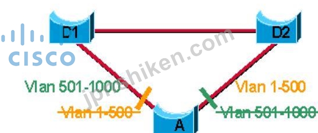
1500のVLANが定義されており、VLAN識別子に基づいて2つの主要な集約ポイントを介して共有トラフィックをロードする必要があるループレススイッチネットワークを実装するには、どのような方法が推奨されますか?
正解:B
Explanation
Where to Use MST This diagram shows a common design that features access Switch A with 1000 VLANs redundantly connected to two distribution Switches, D1 and D2. In this setup, users connect to Switch A, and the network administrator typically seeks to achieve load balancing on the access switch Uplinks based on even or odd VLANs, or any other scheme deemed appropriate.
https://www.cisco.com/c/en/us/support/docs/lan-switching/spanning-tree-protocol/24248-147.html

- 質問一覧「147問」
- 質問1 EIGRP OTP実装でのLISPカプセル化について正しい説明はどれです...
- 質問2 2つの魔女のアクションは、同じハイパーバイザーで実行されてい
- 質問3 展示を参照してください。 (Exhibit) エンジニアはアクセス制御...
- 質問4 クラウドインフラストラクチャの展開ではなく、オンプレミスイン
- 質問5 展示を参照してください。 (Exhibit) エンジニアがSwitch1とSwit...
- 質問6 展示を参照してください。 (Exhibit) 放射パターンはどのタイプ...
- 質問7 Cisco EAP-FASTについての事実は何ですか?
- 質問8 展示を参照してください。 (Exhibit) 展示で使用されているネッ...
- 質問9 準仮想化の特徴は何ですか?
- 質問10 複数のルーターが同じLANセグメントにある場合、どのルーターがI...
- 質問11 同期EEMアプレットポリシーを使用して、アクティブなコンソール...
- 質問12 エンジニアは、TCPヘッダーにACKを含むパケットを許可するACLを...
- 質問13 特性を左側から右側の正しいインフラストラクチャ展開タイプにド
- 質問14 PIMはマルチキャストトラフィックを転送するためにどのようなメ...
- 質問15 ブルート攻撃からREST APIを保護し、影響を最小限に抑えるために...
- 質問16 同様のネットワーク設定を持つデバイスに適用できる一般的な構成
- 質問17 エンジニアは、高速移行を有効にしてWLANを構成します一部のレガ...
- 質問18 ワイヤレスユーザーは、ワイヤレスネットワークから頻繁に切断さ
- 質問19 展示を参照してください。 (Exhibit) エンジニアは、ルーターか...
- 質問20 Cisco DNA Centerを完全にアップグレードするには、どの2つの手...
- 質問21 Cisco SD-WANルータとvSmartコントローラ間で使用されるコントロ...
- 質問22 Cisco TrustSecがネットワーク全体でスケーラブルで安全な通信を...
- 質問23 EIGRPメトリックはOSPFメトリックとどのように異なりますか?...
- 質問24 Cisco DNA Centerプラグアンドプレイ環境で、デバイスに未請求の...
- 質問25 IP SLAについて正しいものはどれですか。 (2つ選択してください...
- 質問26 BGPベストパスアルゴリズムが使用する正しいEBGPパス属性リスト...
- 質問27 Cisco SD-Access展開でのファブリックコントロールプレーンノー...
- 質問28 展示を参照してください。 (Exhibit) エンジニアは、ルーターR3...
- 質問29 SD-WAN展開で、vSmartコントローラーのどのアクションが原因です...
- 質問30 (Exhibit) 展示を参照してください。 FastEthernet0 / 2に接続さ...
- 質問31 Cisco DMA Centerから発信され、ファブリックアンダーレイスイッ...
- 質問32 JSON Webトークンの構造は何ですか?
- 質問33 説明を左側から右側の正しいQoSコンポーネントにドラッグアンド...
- 質問34 タイプに関する仮想マシンのIPおよびMAC割り当て要件を説明する...
- 質問35 展示を参照してください。 (Exhibit) エンジニアはSPANセッショ...
- 質問36 専用のコンピューティング、メモリ、ストレージリソースと、完全
- 質問37 展示を参照してください。 (Exhibit) SwitchCはHRとSalesをコア...
- 質問38 エンジニアがVRRP用にGigabitEthernet1 / 0/0を構成しています。...
- 質問39 Cisco NQFWのどの展開オプションがスケーラビリティを提供します...
- 質問40 Ansible管理対象ノードの要件は何ですか?
- 質問41 展示を参照してください。 (Exhibit) エンジニアがスイッチSW1と...
- 質問42 SD-Access展開でファブリックエッジノードはどの機能を実行しま...
- 質問43 展示を参照してください。 (Exhibit) エンジニアは、AS 200を出...
- 質問44 プロトコルに依存しないマルチキャストはどのように機能しますか
- 質問45 VXLANのVTEPの機能はどのアクションですか?
- 質問46 ElGRPでサポートされているが、OSPFではサポートされていない機...
- 質問47 VRRPについて正しいのはどの2つですか? (2つ選択してください...
- 質問48 WI-FIネットワークの2つの一般的な干渉源は何ですか? (2つ選択...
- 質問49 Cisco SD-WANノード間に安全なコントロールプレーン隣接関係を確...
- 質問50 Cisco DNA Centerは、ネットワークを介したアプリケーションの配...
- 質問51 セカンダリWLCの責任は何ですか?
- 質問52 エンジニアは設計ワークフローを使用して、Cisco DNA Centerに新...
- 質問53 AAA認証に関する2つの説明のうち正しいものはどれですか。 (2つ...
- 質問54 2002 :: / 16予約アドレススペースを使用する動的トンネルに依存...
- 質問55 サイトのEIDからRLOCへのマッピングの発行を担当するLISPデバイ...
- 質問56 HSRPについて正しい説明はどれですか。 (2つ選択してください)...
- 質問57 展示を参照してください。 (Exhibit) ネットワークエンジニアが...
- 質問58 Cisco SD-WAN展開のデータポリシーは何ですか?
- 質問59 (Exhibit)
- 質問60 Cisco SD-WANのオーケストレーションプレーンを処理するコンポー...
- 質問61 RIBとFIBの2つの違いは何ですか? (2つ選択してください。)...
- 質問62 どのIP SLAオペレーションで、リモートエンドでIP SLAレスポンダ...
- 質問63 顧客がいくつかの小さな支店を持っており、CAPWAPを使用してロー...
- 質問64 ハイパーバイザーが仮想マシンで利用できるようにする必要がある
- 質問65 データモデリング言語の使用方法
- 質問66 展示を参照してください。 (Exhibit) WLCのインターフェイスがRA...
- 質問67 Wi-Fiネットワークに干渉を引き起こす2つのソースはどれですか?...
- 質問68 展示を参照してください。 (Exhibit) エンジニアは、ホスト間の...
- 質問69 ダウンタイムなしで仮想マシンをあるホストマシンから別のホスト
- 質問70 EIGRPでサポートされているが、OSPFではサポートされていない機...
- 質問71 NTPを保護するために使用できるメカニズムはどれですか。 (2つ...
- 質問72 (Exhibit) 展示を参照してください。両方のコントローラーは同じ...
- 質問73 デバイスパスワードを暗号化するために、シークレットパスワード
- 質問74 展示を参照してください。 (Exhibit) エンジニアが、インターフ...
- 質問75 展示を参照してください。 (Exhibit) これらのコマンドは、スイ...
- 質問76 展示を参照してください。 (Exhibit) コードスニペットは何を達...
- 質問77 展示を参照してください。 (Exhibit) この構成の2つの効果は何で...
- 質問78 YANGデータモデルで使用される2つのプロトコルはどれですか? (...
- 質問79 YANGのようなデータモデリング言語の利点は何ですか?
- 質問80 展示を参照してください。 (Exhibit) 出力は、スイッチのスパニ...
- 質問81 エンジニアは、パケット間の遅延変動に敏感な新しいアプリケーシ
- 質問82 NetFlowフローモニタリングの2つの機能は何ですか? (2つ選択し...
- 質問83 左側のLIPSコンポーネントを、右側の正しい説明にドラッグアンド...
- 質問84 展示を参照してください。 (Exhibit) この構成の2つの効果は何で...
- 質問85 展示を参照してください。 (Exhibit) サンプラ機能をルータのFle...
- 質問86 展示を参照してください。 (Exhibit) Link1は銅線接続で、Link2...
- 質問87 展示を参照してください。 (Exhibit) 技術者がmonitor session 1...
- 質問88 ネットワークは、デュアルスタックアプローチを使用してIPV4から...
- 質問89 LISPネットワークアーキテクチャとプロトコルが使用する名前空間...
- 質問90 展示を参照してください。 (Exhibit) すべてのユーザーに対して...
- 質問91 クラウド展開はオンプレミス展開とどのように異なりますか?
- 質問92 タイプ1ハイパーバイザーである2つのエンティティはどれですか?...
- 質問93 ワイヤレスコンサルタントが、1000人の学生を対象とした講堂用の...
- 質問94 (Exhibit) 展示を参照してください。 PC-1はポート8080でWebサー...
- 質問95 IPベースのアクセスコントロールポリシーを展開するときに、Cisc...
- 質問96 展示を参照してください。 (Exhibit) PE3に新しいVRFを作成しま...
- 質問97 エンジニアは、CiscoIOSルータでHSRPグループ300を設定する必要...
- 質問98 従来の3層トポロジでは、エンジニアはスイッチをルートブリッジ
- 質問99 シスコエクスプレスフォワーディングテーブルとFIBはどのように...
- 質問100 syslogにTLSを使用する場合、デフォルトのポートへのメッセージ...
- 質問101 CLIを使用して、Cisco IOS XEを実行するコントローラーを構成し...
- 質問102 SSOはHSRPとどのように連携してネットワークの中断を最小限に抑...
- 質問103 RESTAPI認証メソッドを左側から右側の説明にドラッグアンドドロ...
- 質問104 SNRを計算するために必要な2つの情報はどれですか。 (2つ選択し...
- 質問105 ワイヤレスLANコントローラを検出するために入力しているAPが使...
- 質問106 VRF-Liteの主な機能は何ですか?
- 質問107 Cisco SD-WANの単一管理面のコントローラはどれですか。...
- 質問108 送信機の電力レベル、ケーブル損失、アンテナゲインの数値を使用
- 質問109 ヘッドエンドルーターとリモートルーター間の動的GREについて正...
- 質問110 YANGデータモデルが使用されていることを推測するプロトコルはど...
- 質問111 ワイヤレスCiscoSD-Access展開では、ユーザが単一のWLCを使用し...
- 質問112 Cisco SDWAN展開でのvBondの機能は何ですか?
- 質問113 Edgeデバイスのオンボーディングプロセス中にSTUNサーバーとして...
- 質問114 展示を参照してください。 (Exhibit) PVST +を実行しているスイ...
- 質問115 特性を左側から右側の正しいインフラストラクチャ展開タイプにド
- 質問116 ローカルルーターは、アクティブ状態のEBGPネイバーを示します。...
- 質問117 マルチキャストRPについて正しい説明はどれですか。
- 質問118 展示を参照してください。 (Exhibit) HQルーターとBRルーターの...
- 質問119 ある会社には、SSOを使用する既存のCisco 5520HAクラスタがあり...
- 質問120 エンジニアがサンプルコードを実行すると、端末はこの出力を返し
- 質問121 展示を参照してください。 (Exhibit) 通常の操作で「tommy」のユ...
- 質問122 LISPでサポートされている2つのコンポーネントはどれですか? (...
- 質問123 どのDHCPオプションがCAPWAPAPにワイヤレスコントローラのアドレ...
- 質問124 クライアントデバイスは、アトリウムの異なるフロアにあるアクセ
- 質問125 ログファイルの日付の横に*が含まれるのはなぜですか?
- 質問126 ログイン方法は、これらのパラメーターを使用してルーターのVTY...
- 質問127 Cisco SD-Accessファブリックの推奨MTUサイズはどれくらいですか...
- 質問128 Cisco SD-Accessソリューションのコントロールプレーンノードの...
- 質問129 3つの有効なHSRP状態は何ですか? (3つ選択してください)...
- 質問130 1500のVLANが定義されており、VLAN識別子に基づいて2つの主要な...
- 質問131 ネットワークエンジニアがFlexibleNetflowを設定し、次のコマン...
- 質問132 タイプ1ハイパーバイザーの代わりにタイプ2ハイパーバイザーを使...
- 質問133 レイヤー3デバイスで冗長ルートプロセッサの障害が発生した後、
- 質問134 ポート80を除く宛先ポート範囲が22〜433のTCPトラフィックのみを...
- 質問135 説明を左側から右側に説明されているルーティングプロトコルにド
- 質問136 お客様は、新しいキャンパスでWi-Fi6グリーンフィールド展開のイ...
- 質問137 展示を参照してください。 (Exhibit) R1はR3fa0 / 1インターフェ...
- 質問138 Linuxを実行しているサーバーは、中小企業向けにDNSおよびDHCPサ...
- 質問139 展開中、ネットワークエンジニアは、音声トラフィックがネットワ
- 質問140 Cisco SD-Accessソリューションでは、Identity Services Engine...
- 質問141 このインターフェイス構成に基づいて、OSPF隣接の予想される状態...
- 質問142 (Exhibit) 展示を参照してください。エンジニアは、クライアント...
- 質問143 NTPの実装時に使用できるセキュリティ機能はどれですか。 (2つ...
- 質問144 展示を参照してください。 (Exhibit) Cisco DNA Centerは、クラ...
- 質問145 sync yesオプションを使用すると、EEMアプレットのどの変数が設...
- 質問146 EEMに登録され、オンデマンドまたは手動で実行されるEEMアプレッ...
- 質問147 Cisco DNA Centerが提供するIntent APIを定義する2つの特性はど...
